Simple Line Follower Part II — Sensor array & electronics
This is the second part of a three part series showing how to a make a simple line following robot. We don’t have a name for this robot, I simply call him SLFv1. I plan on making a second version that is less expensive to build, but this version is only around $30-40 dollars in material cost. You can find free blueprints to make this robot in part 1 and the robot BOM. This part of the free robot plans deals with the schematic for the sensor array and the micro-controller electronics. This line follower uses four IRLED’s (Infrared LED) and four photo-transistors. The infrared LED emits lights in the infrared spectrum (not visible to the naked eye) which bounces off the floor. This reflected light is picked up by the photo-transistor which is wired to a digital input on the microcontroller. Here’s a simple free schematic of the robot sensor array:

Simple line follower general schematic (PDF format)
As you can see this a very simple circuit, the IRLED is connected to +5 volts using a 360 ohm resistor and the phototransistor is connected to +5 volts using a 47K ohm resistor. To intercept the signal off the phototransistor, you connect a wire between the resistor and the phototransistor and send this signal to a DIO (Digital I/O) input line on the microcontroller.
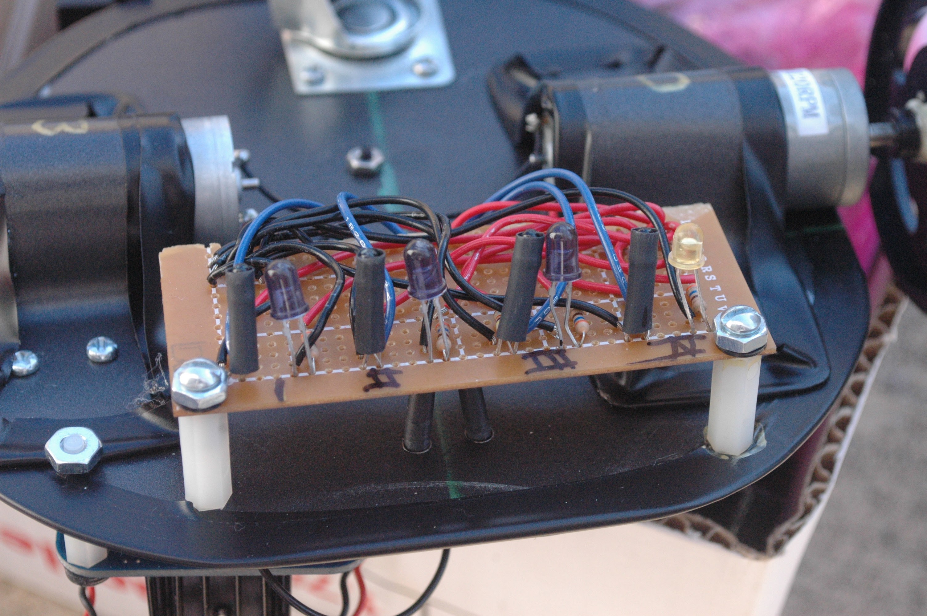
We used four pairs of IRLED and phototransistors for this simple line follower robot. Here’s the complete schematic:
